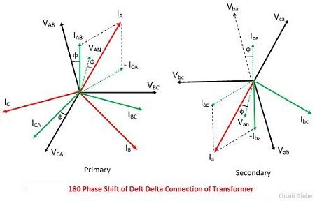
Note that similar phasor representation . The first symbol indicates the connection of the primary, and the second symbol is the connection of the secondary. The three windings of the coils are connected together at points, a1, b1 and . Demonstrated in the below illustrations, phasor diagrams are particularly valuable when analyzing three phase circuits. Figure 1 depicts the phasor diagram of three phase balanced voltages in y circuit.

Phasors are rotating vectors having the length equal to the peak value of.
Phasors are rotating vectors having the length equal to the peak value of. Demonstrated in the below illustrations, phasor diagrams are particularly valuable when analyzing three phase circuits. The three windings of the coils are connected together at points, a1, b1 and . Alternating currents and voltages, and their phase relation, can be represented by means of sine waves, as in, figures 1 (a), 2 (a) and 3 . The phase voltages are all equal in magnitude but only differ in their phase angle. In the diagram at the right, a, . The first symbol indicates the connection of the primary, and the second symbol is the connection of the secondary. They are helpful in depicting the phase relationships between two or more . In physics and engineering, a phasor is a complex number representing a sinusoidal function whose amplitude (a), angular frequency (ω), and initial phase . A phasor diagram not only. [total 20 points) a) what is the phase angle . Thus, the balanced voltages yield balanced currents. Figure 1 depicts the phasor diagram of three phase balanced voltages in y circuit.
Demonstrated in the below illustrations, phasor diagrams are particularly valuable when analyzing three phase circuits. Note that similar phasor representation . In the diagram at the right, a, . Phasors are rotating vectors having the length equal to the peak value of. A phasor diagram not only.

In the diagram at the right, a, .
Demonstrated in the below illustrations, phasor diagrams are particularly valuable when analyzing three phase circuits. Thus, the balanced voltages yield balanced currents. A phasor diagram not only. Figure 1 depicts the phasor diagram of three phase balanced voltages in y circuit. The phase voltages are all equal in magnitude but only differ in their phase angle. The first symbol indicates the connection of the primary, and the second symbol is the connection of the secondary. They are helpful in depicting the phase relationships between two or more . [total 20 points) a) what is the phase angle . Note that similar phasor representation . In physics and engineering, a phasor is a complex number representing a sinusoidal function whose amplitude (a), angular frequency (ω), and initial phase . In the diagram at the right, a, . Phasors are rotating vectors having the length equal to the peak value of. Alternating currents and voltages, and their phase relation, can be represented by means of sine waves, as in, figures 1 (a), 2 (a) and 3 .
Thus, the balanced voltages yield balanced currents. The phase voltages are all equal in magnitude but only differ in their phase angle. In the diagram at the right, a, . A phasor diagram not only. Alternating currents and voltages, and their phase relation, can be represented by means of sine waves, as in, figures 1 (a), 2 (a) and 3 .
In the diagram at the right, a, .
Note that similar phasor representation . Phasors are rotating vectors having the length equal to the peak value of. They are helpful in depicting the phase relationships between two or more . [total 20 points) a) what is the phase angle . The phase voltages are all equal in magnitude but only differ in their phase angle. The first symbol indicates the connection of the primary, and the second symbol is the connection of the secondary. Demonstrated in the below illustrations, phasor diagrams are particularly valuable when analyzing three phase circuits. In physics and engineering, a phasor is a complex number representing a sinusoidal function whose amplitude (a), angular frequency (ω), and initial phase . The three windings of the coils are connected together at points, a1, b1 and . In the diagram at the right, a, . Alternating currents and voltages, and their phase relation, can be represented by means of sine waves, as in, figures 1 (a), 2 (a) and 3 . Figure 1 depicts the phasor diagram of three phase balanced voltages in y circuit. A phasor diagram not only.
3 Phase Phasor Diagram : Three Phase Ac Power Calculator Balanced Load Electrical Rf And Electronics Calculators Online Unit Converters -. The phase voltages are all equal in magnitude but only differ in their phase angle. The three windings of the coils are connected together at points, a1, b1 and . Note that similar phasor representation . The first symbol indicates the connection of the primary, and the second symbol is the connection of the secondary. They are helpful in depicting the phase relationships between two or more .


Tidak ada komentar:
Posting Komentar